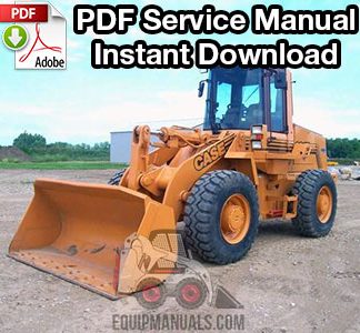
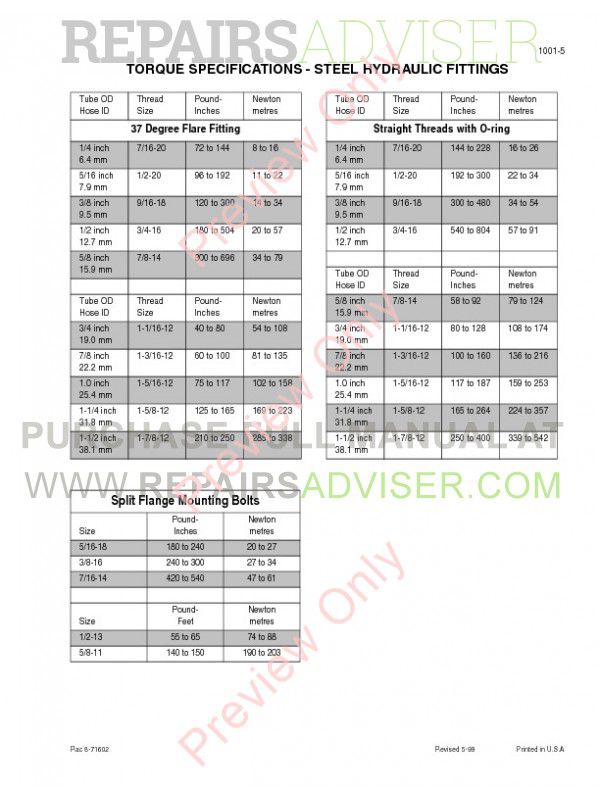
The Case 621B and 721B service manual covers comprehensive service, repair and troubleshooting procedures for the wheel loader. This service manual has over 1,800 pages of technical information with illustrations for professional and DIY mechanics. View the service manual on your tablet, smartphone or computer and save time and money on repairs. Service Repair Manual For Case 621B, 721B. Include detailed step by step Instructions, diagrams, illustrations for disassembly and assembly. Make an easy any repair, overhaul, testing, adjustment, teardown, replacement and change, inspection.


INSTANT DOWNLOAD (add to cart)
Case 621b Loader Service Manual
1,000+ pages, bookmarked, Searchable, Printable, high quality PDF
“Case 621C/721C Loader Service Manual” – 824 pages
“6-30480NA – Case 721C Wheel Loader Operator’s Manual” – 288 pages
“6-1231.pdf – Case 621C-721C Loaders Operator’s Manual” – 281 pages
“721C EWD & Hydraulic Schematic.pdf”

Complete workshop & service manual with electrical wiring diagrams for Case 621C/721C Loader. It’s the same service manual used by dealers that guaranteed to be fully functional and intact without any missing page.
This Case 621C/721C Wheeled Loader service & repair manual (including maintenance, overhaul, disassembling & assembling, adjustment, tune-up, operation, inspecting, diagnostic & troubleshooting…) is divided into different sections. Each section covers a specific component or system with detailed illustrations. A table of contents is placed at the beginning of each section. Pages are easily found by category, and each page is expandable for great detail. The printer-ready PDF documents work like a charm on all kinds of devices.
EXCERPT:
INFORMATION AND DIAGNOSTIC CENTER
Many of the machine functions can be displayed on the Programmable Information Center. It can be programmed to display all functions, or only the functions important to the operator. The following functions can be displayed on the Information Center, refer to Figure 2:
FIGURE 2. INFORMATION CENTER AND TRANSMISSION DISPLAY
1. DIRECTION (F-N-R) 4. REQUESTED GEAR (1, 2, 3, 4)
2. TRANSMISSION DISPLAY 5. ACTUAL GEAR BARS
3. DISPLAY CENTER 6. TRANSMISSION MODE (A OR BLANK)
Hourmeter
The hourmeter displays the accumulated running time of the engine in hours and tenths of an hour with an “hour glass” symbol.
Tachometer
The tachometer displays the engine speed in revolutions per minute along with a “r/min” symbol.
Speedometer
The speedometer displays the ground speed in either kilometers per hour (km/h) or miles per hour (mph) along with either a “km/h” or “mph” symbol.
Engine Coolant Temperature
Displays the engine coolant temperature in Celsius with the engine coolant temperature bar graph flashing. See page 10 for a detailed description of the bar graph function.
Engine Oil Pressure
Displays the engine oil pressure in kilopascals (kPa) with the engine oil pressure bar graph flashing. See page 10 for a detailed description of the bar graph function.
Fuel Level
Displays the fuel level in percent remaining in the tank with the fuel level bar graph flashing. See page 10 for a detailed description of the bar graph function.
…
Case 621 Wheel Loader Manual

621e Case Loader Parts Manual


